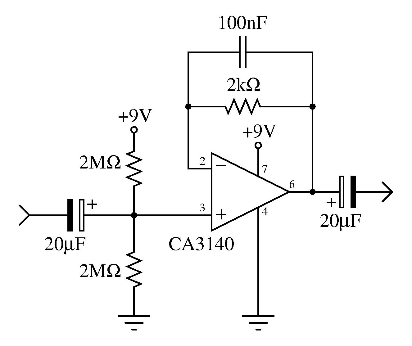
Sound Card Oscilloscope

If you use diodes, or zeners, then it's good to confirm the transfer ratio of input to output, as the diodes wil influence the ratiol before the nominal 0. Masterpieces Of Modern Soul Volume 3 Rarest here. 7V 'clip' per diode. You should also try to determine the voltage level at which your soundcard starts to clip the incoming signal (eg. Look at the frequency spectrum of a sine wave and notice when the harmonics become significant - eg.
With TrueRTA). Then you can tweak your probe to give the largest input voltage swing before external clipping. You should also try and introduce hf filtering.
The Kelalis-king-belman Textbook Of Clinical Pediatric Urology. Sound card oscilloscope. Discussion in 'General Electronics Chat' started by juantravel, Jun 22, 2010. Find great deals on eBay for soundcard oscilloscope and 4tb external. Shop with confidence. The sound card or motherboard sound chip does a passable job of converting a voltage to digital data, and software can be had free or for a few bucks that can display the data on the screen. Oscilloscope Cable:A three conductor shielded cable with a regular 3.5mm stereo phono plug will do the job. Download Sound Card Oscilloscope for Windows now from Softonic: 100% safe and virus free. More than 182 downloads this month. Download Sound Card Oscilloscope latest.
Its quite easy to kill a soundcard (don't ask me how I know). Blackberry Os For 9300. Wether the resistors are right or not depends on the intended application, which you said zilch about. Audio inputs usually has an impedance, which will modify the external divider ratio. Your voltage numbers disagree, but going by one of the sets input impedance is 52k. Your modified diagram is incorrect.
I said to replace the 82k resistors (as positioned in the original diagram, of course). And as Tim says, the clipping will be soft, and it's not beneficial to clip it externally at a lower level than the card clips at itself. I like what I have read so far and I wanted to add that you may see vastly different results just based on the frequency of the input signal you are using.
Do you already know the frequency response of th input in question? We know it is band pass because audio inputs are usually AC coupled so do you know at what frequency the input is in passband 10Hz, 50Hz,100Hz.? Perhaps if you have the ability you should characterize the frequency response then it may make better sense when you calculate your input limiting. Remember that your input resistors add thermal noise.